DEVELOPMENT – FURNACE SIDINGS FOOTBRIDGE (STEP 1.3.2) – PAGE
2
Click HERE to return to Page 1
More news on the ‘Hinckley’
footbridge (uploaded 12 June 2010)
It seems rather odd, but for some reason, updates
regarding progress on the Hinckley footbridge have been noticeable by their
absence. That is not, by any means, to
say that there has been no progress, far from it, though much of it has been
progressive in nature and with no obviously photogenic consequences that would
justify many images on this page. It has
been fifteen months since our last report, and the work has in fact been quite
dramatic. In a nutshell:
(a) The second tower has been
assembled and has been erected on site, though cannot yet be bolted down till
the main deck is installed. The tower
remains to be painted.
(b) The second tower flight walls
were sent to Barry Docks for welding and reconstruction. They have since been returned to Blaenavon
and are now in position ready to be bolted to No.2 tower, however this cannot
happen till the tower itself is bolted down, and this, in turn cannot happen
till the main deck is bolted into place. They still remain to be painted.
(c) the newel posts for No.2
flight have been painted and remain in the yard.
(d) the big news is that the
extensive, and seemingly endless, welding work on the main deck is essentially
complete, and painting is well under way.
Wooden planking for the main deck and its related ascents (and for the
two flights) is to be ordered shortly. A
very few detailed welding jobs remain.
Now that it is becoming obvious that what started in
October 2006 as an ugly collection of rusting parts is about to emerge as a
swan (insofar as anything of LNWR design could ever be so described), less than
four years later, the political spotlight is undoubtedly turning to the
footbridge and there seems to be a gathering collective political will to get
the bridge erected during the summer. It
could be that the next update will the last on the footbridge and will record
its final lifting into place – and some images from a new viewpoint! Anyway, here are 22 images telling the story
to date.
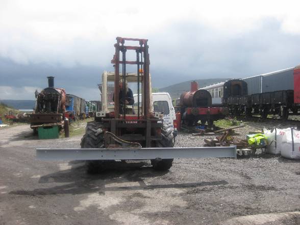
Carrying tower No.1 complete from assembly on site
up to the platform was a difficult job, and it was decided to assemble tower
No.2 on the essentially unused platform 2.
Here the first of the legs makes the journey from the site yard
2351 – 26 Apr 09
|
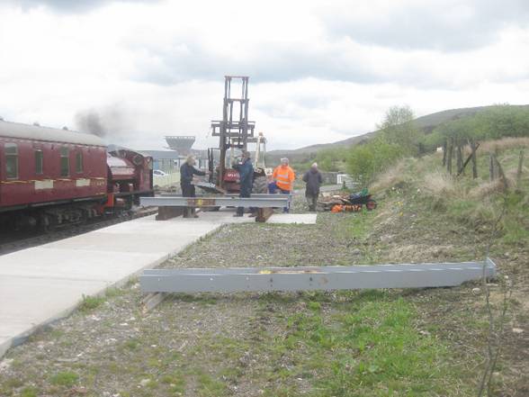
The components start to arrive on platform 2. One of the newly primed legs in seen in the
foreground.
2398 – 3 May 09
|
Assembly begins – two legs are joined by three
heavy but attractive cast trusses. We
has always been worried that we might break one of the castings, which would
as likely as not would have rendered the whole bridge scrap, but, to date,
there have been no accidents
2415 – 3 May 09
|
With just one truss to go the assembly approaches
completion
2822 – 15 June 09
|
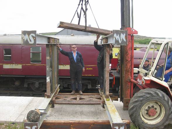
The other half of the fabrication team, George P,
keeps an eye on the proceedings as the last of the trusses is lowered into
position. As a note of explanation the
tower marked NW is in the south west, and vice versa. The markings relate to the positions at Hinckley, which have been-
re-orientated so that the stair flight points the opposite way.
2837 – 21 June 09
|
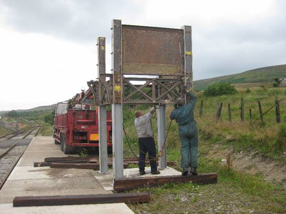
The same scene from a differing viewpoint. Derek steadies the frame and slackens some
bolts as Wayne E on the Manitou adjusts the final truss into place
2838 -21 June 09
|
The lift begins!
Platform 2 is tested well beyond its design limit as a lorry load of concrete
blocks, which happened to be passing, is commandeered into lifting tower No.2
with its hi-ab.
3055 – 22July 09
|
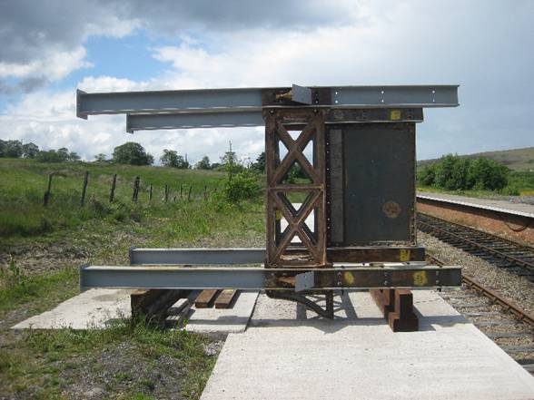
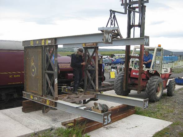
The tower teeters on its balance point. Note that the attitude of the tower is incorrect,
as, once swinging, it has to be turned through ninety degrees so that the
open side fitted with spandrels points across the rails to support the main
deck and the triangular gussets point southwards to support the stair flights
3056 – 21 June 09
|
All that worry about getting the tower into
position and the whole job only took five minutes. Men from the local haulage firm remove the
lifting tackle from the bridge
3059 - 21July 09
|
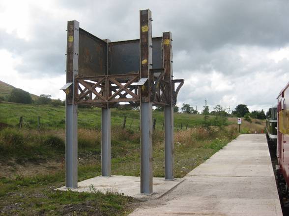
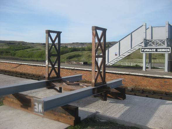
Looking
the other way a few days later we see tower No.2 in repose. It is very close to its final position, but
needs to come in by 30mm after the main deck is slotted in.
3113
– 25 July 09
|
With tower No.2 in position it was now time to concentrate
on the main deck. There had already been some progress but now all bridge
effort could be directed to the main deck.
Unfortunately there were many interruptions, distractions, and
diversions, but despite these the fabrication team always managed to gravitate
back to the bridge, so that although progress was slow, it continued to move
inexorably forward.
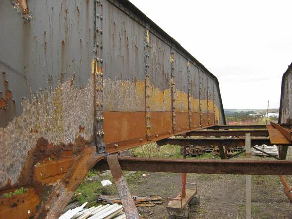
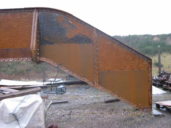
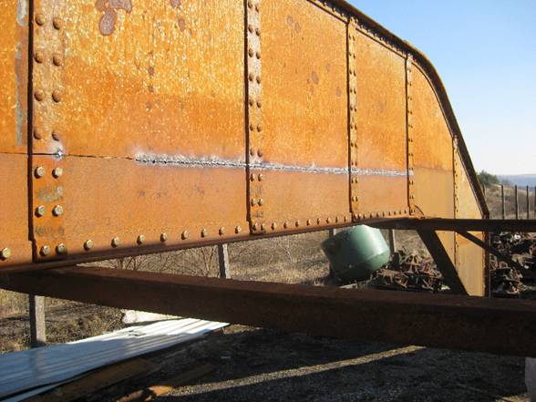
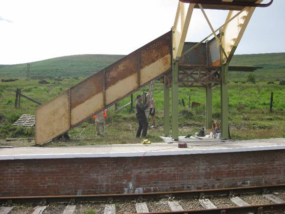
Due to the proximity of damp timber to the bottom
flange of the bridge (which would have supported the timber planking) the flange
had almost completed rotted away. This
is the ‘Achilles heel’ of this type of footbridge. This corrosion demanded the complete
replacement of the bottom flange and of the first six inches or so of the
side panel. Here the new parts have
been bolted, but not yet welded into place
0092 – 16 Aug 09
|
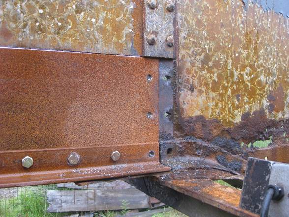
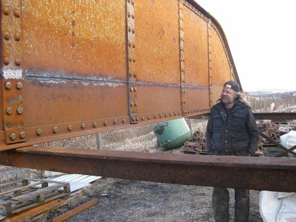
Here’s a technical close-up of work in
progress. Nothing has been welded yet,
and the rivets have been replaced by high tensile friction bolts – not pretty
but effective. The corrosion on the
ascent is also severe but the bottom flange will live to fight another day,
though some further localised work in this area will be necessary.
0099 – 23 Aug 09
|
As can be seen in preceding images, corrosion of the
‘ascent’ panels in severe, but here but the bottom flange is acceptable. The technique used here is to sandwich the
defective plate between a new inner and outer plate. Here two plates can be seen tack welded
into place.
0649 – 8 Dec 2009
|
From further back it will be appreciated that the
sandwich technique employs no less than sixteen plates. The complex profile was obtained by means
of tracing through a roll of the webmaster’s wallpaper!
0658 – 14 Dec 09
|
Snow! With only
a sputtering arc to keep him warm, Derek B completes yet another two of the
sixteen panels.
0694 – 22 Dec 2009
|
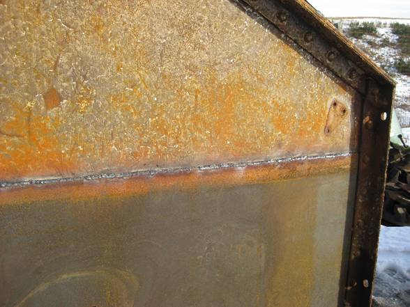
The work continues by making a waterproof weld
along the top to keep the rain out. The bottom weld is intermittent in order
to allow any condensation to drain away
0807 – 17 Jan 2010
|
Along the ‘six-inch’ line a very deep penetrating
weld is required. The strengthening
pillars need particularly careful treatment when they are welded.
0990 - 7 Mar 2010
|
Derek B surveys the advancing weld. The nearest pillar has been ground to
confirm the quality of the weld
1017 – 14 Mar 2010
|
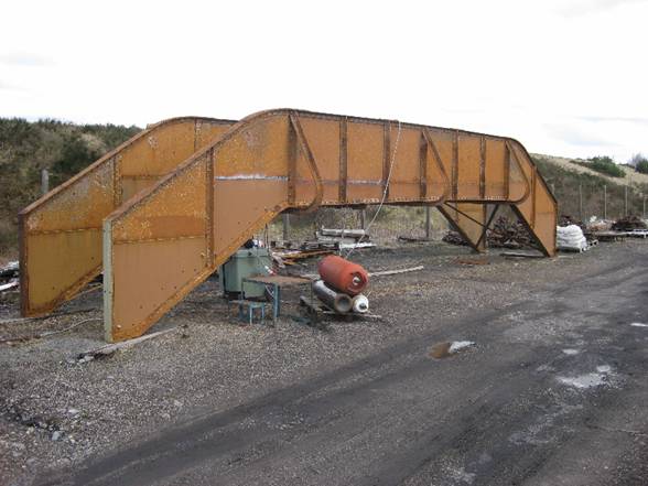
The plate
work is just about complete, but two stretcher bars under the main deck need
cutting off and replacing.
1103.-.4 Apr 2010
|
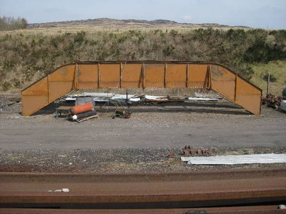
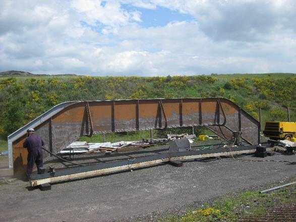
Here, in its full glory, the main deck. The repairs have left small scars but this
is not expected to seriously detract from the overall appearance once the
bridge is painted.
1132 – 10 Apr 2010
|
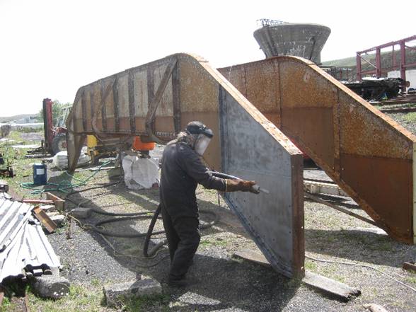
Now it really does look as if completion is very
close. Derek B again, grit blasting
off any remaining paint, and surface rust, in readiness for the first primer
paint layer.
1294 – 30 May 2010
|
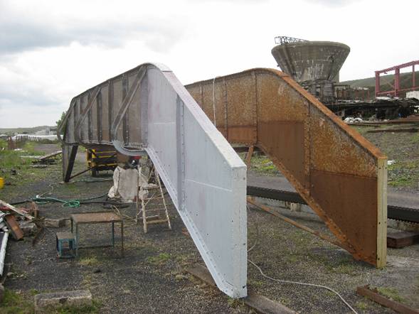
Access to the main deck for maintenance or
painting will be difficult once it is in position, so plenty of high
phosphate primer is now quickly applied to such surfaces as have been
de-rusted.
1302 - 6 June 2010
|
So that is the current situation. We still have to install the cleats, which support
the footsteps, and we are having new brackets cast which will support new
handrails. It is expected that the
timber for the footsteps and decking will be ordered very shortly and these
must be installed. Since many of the
timbers will have profiled ends in order to provide clearance for bolt heads
and other bits and pieces this could prove to be quite time-consuming, and has
been recommended that this work is completed before the main deck is finally
lifted into position, in order to provide dimensional stability.
Final
assembly and commissioning (21 October 2010)
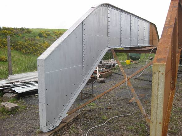
Progress with the high phosphate primer now
extends most of the way down the inside.
Also, as an added safety feature a flat sheet has been fitted along the
midline of the main deck and can just be seen here. Now, in the case that in about 100 years
time, the side angle should fail again, there is no chance of the timber
being completely unsupported.
1306 – 8 June 2010
|
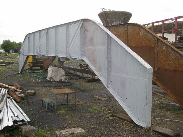
Primer coat now completely covers the outside of
the east side of the main deck. The
area to be painted was not small – there are of course, four sides to be
painted – and several weeks were needed to dodge the showers and complete the
work.
1307 – 8 June 2010
|
This was a lucky shot, caught with the light in
just the right position to show the prodigious amount of work along the
bottom edge of the main deck. All the
rivets had to be burnt and punched out., the bottom cut away, the original
angle discarded, new plate and angle fitted, an exceptionally long high
quality double sided weld made, any number of friction bolts installed, and
all the pillars reconstructed – and then the whole process had to be repeated
on the other side!
1308 – 13 June 2010
|
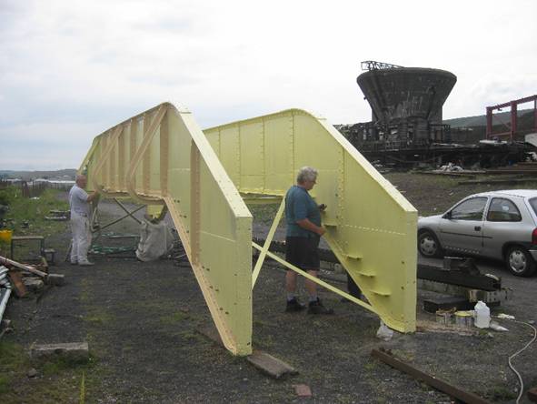
Another week goes by, and the main deck is covered
in primrose coloured undercoat. On the
left, master painter Bev W starts on the cream coloured top coat. On the right, and with Derek hidden on the
far side, Wayne E makes a start attaching the cleats to the sides of the
ascents.
002 – 18 June 2010
|
Unlike the level portion of the main deck, repairs
to the steelwork on the ascents took the form of ‘sandwiching’ the damaged
plate between two outer plates. Here a
watertight weld held the top. The sides
were bolted as were the bottoms, though the bottom were able to make use of
the cleat bolts. The open sides and
bottoms were to allow the escape of condensation and so reduce corrosion
0003 – 18 June 2010
|
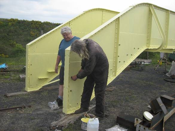
For a change we see the south end of the bridge,
but with the same dogged workers fitting more bolts into the sandwicjh
plates. As soon as the bolts are
fitted and finally nipped up it is imperative that they are given a thick
coat of paint – this is one area where we cannot afford corrosion.
0004 – 18 June 2010
|
We pause now to record an important step forward in
the restoration of the footbridge– the removal of the main deck and fitting
between the towers. All this group of images
are from the camera of volunteer Martin Hope.
The date is 20th July 2010, four
years and four months after the date when the main deck arrived from Rushden in
Northamptonshire and was dropped into this position, to whit,16 November 06
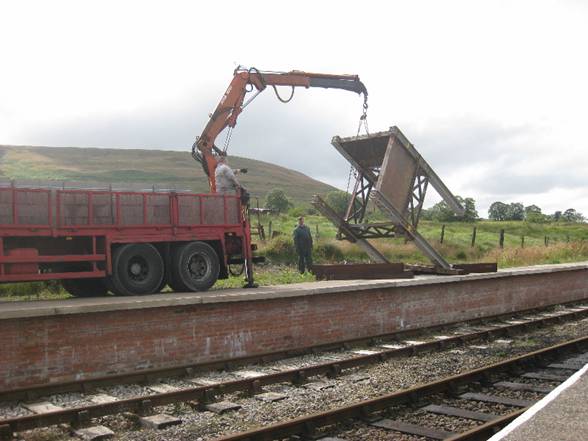
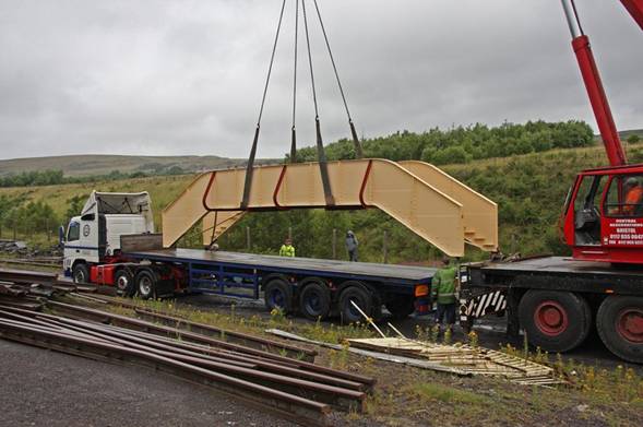
 Although the main deck was unloaded on
arrival with the aid of a modest hi-ab, this rather large crane was used to
load it back onto the lorry. Something
a large as this was not needed for this operation, but read on…. Although the main deck was unloaded on
arrival with the aid of a modest hi-ab, this rather large crane was used to
load it back onto the lorry. Something
a large as this was not needed for this operation, but read on….
Photo:
Martin Hope
|
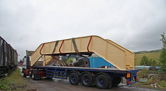
Here the deck, painted in cream with Gulf Red
details, in true BR(M) fashion, being carefully loaded onto the back of the
lorry. The planking had already been
installed on the level section of the main deck, in order to prevent the sides
being squeezed inwards from pressure from the lifting slings
Photo:
Martin Hope
|
The deck makes slow progress out of the Furnace
Sidings on its way up to the station area.
Photo:
Martin Hope
|
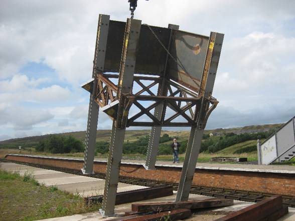
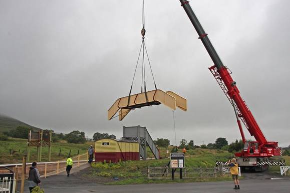
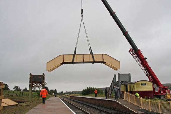
One in the ‘paddock’ behind platform 1, the need for
the big crane becomes apparent as the deck is swung skywards.
Photo:
Martin Hope
|
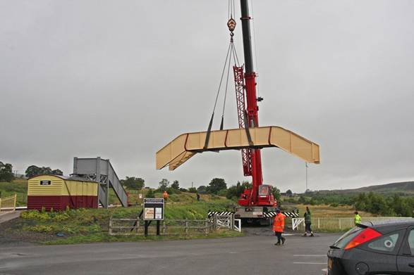
The big crane jibs round as the deck approaches
the twin towers
Photo:
Martin Hope
|
The next stage was rather delicate- the design width
between the towers was planned to be 25mm though in reality, for a variety of
reasons this had increased to 30mm.
Nevertheless the positioning of the main deck was required to be very
precise
Photo:
Martin Hope
|
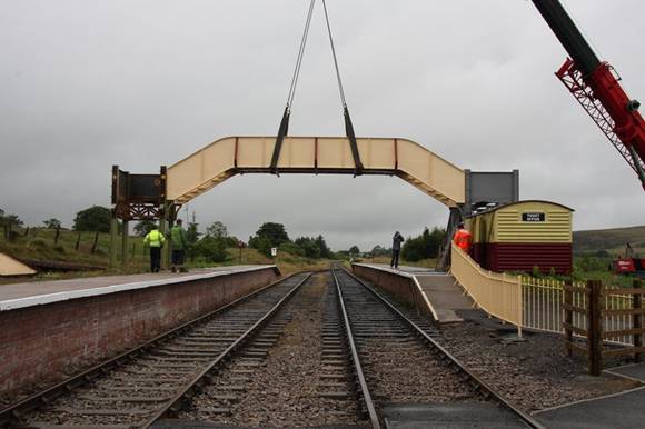
Clearly the crane driver was an operator of
considerable skill as the main deck slotted neatly between the towers without
difficulty and the first tapered ‘podging’ bolts were quickly installed in
order to allow the slings to relax their tension.
Photo:
Martin Hope
|
Wayne and Bev, without delay, replace the podging
bars with final nuts and bolts on tower 1.
This procedure was necessary since tower 1 was fixed. Immediately afterwards tower 2 was inched
the necessary 30mm towards the deck and the final bolts installed there
too. The following weekend tower 2,
like tower 1, was finally grouted into its concrete plinth using specialist
ragbolts.
Photo:
Martin Hope
|
With the main deck in position and with the all-important
joint formal opening of the extension and GWR175 gala looming, pressure to
complete the footbridge was growing. As
a result the two man team of Derek and
George were strengthened by the addition of Bev, Wayne and Ian L. The images below try to tell the story…
Unlike the level portion of the main deck, repairs
to the steelwork on the ascents took the form of ‘sandwiching’ the damaged
plate between two outer plates. Here a
watertight weld held the top. The
sides were bolted as were the bottoms, though the bottom were able to make
use of the cleat bolts. The open sides
and bottoms were to allow the escape of condensation and so reduce corrosion
0003 – 18 June 2010
|
For a change we see the south end of the bridge, but
with the same dogged workers fitting more bolts into the sandwicjh
plates. As soon as the bolts are
fitted and finally nipped up it is imperative that they are given a thick
coat of paint – this is one area where we cannot afford corrosion.
0004 – 18 June 2010
|
|
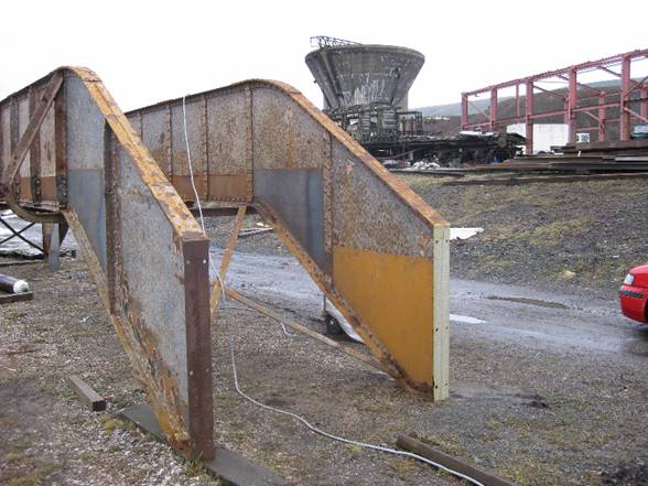
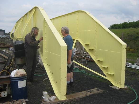
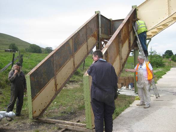
The flight
walls are roughly in place and are bolted loosely into position. The
extensive ‘sandwiching’ is clear to see.
The ascent to the main deck awaits its steps…
0066
– 25
Jul 2010
|
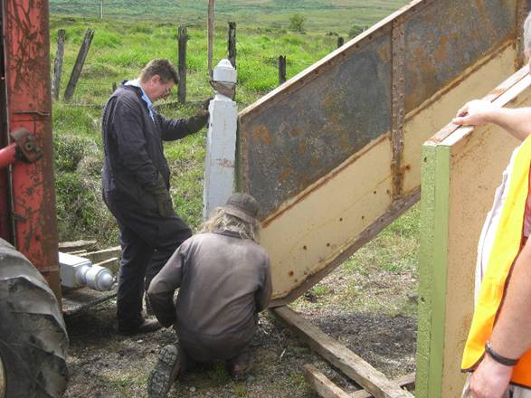
…as
do the stair flights themselves. Derek
and George adjust the bottom of the flight walls to ensure that they are
exactly parallel. It is also necessary
to ensure that the geometry with regard to the platform edge is also
‘spot-on’. Bev and Ian L busy
themselves removing rust flakes prior to the first primer coat going on.
0067 – 25 July 2010
|
|
The cast
newel posts are the next to go on.
These are essentially thick rectangular hollow castings and are
massively heavy. The faithful Manitou peeping
in from the left provided the ‘grunt’ which otherwise would have to be
provided by the volunteers
0070
25
July 2010
|
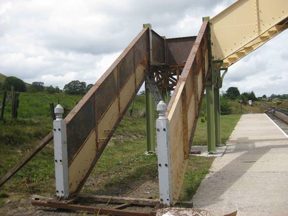
The newel
posts have been bolted into place. It
is just possible to see that each newel post has a pad or foot drilled with four
mounting screws. A temporary steel
angle can be seen in this image, which helps to stabilise the lower ends of
the flight walls, and ensures that the geometry stays correct.
0128
– 1
August 2010/8
|
|
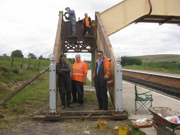
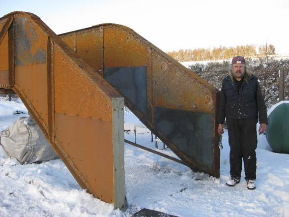
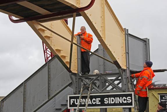
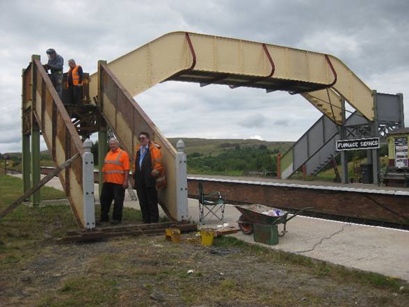
Of course, there
has to be the mandatory group photo and here are most of them posing at the
foot of the erstwhile steps. Meanwhile
yet more volunteers attend to some minor matters on the landing.
0129 – 1 August 2010
|
Despite
volunteers trying to get into yet another shot, this image is intended to
show the complete bridge and shows that it is structurally complete. The steps have to be installed, and the
towers painted, but the end is clearly in site.
0130
– 1 August
|
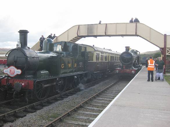
Fast forward now …. It’s the first day of PBR’s
three day extravaganza marking the formal opening of the extension to BHL and
the GWR175 celebrations, the bridge has been brought into use. The steps have been installed, the last
ones being fitted only the day and the towwere have been painted and the
steps brought into use. The steps
were only finally installed on the day before. The bridge seems reasonably
well patronised. Nevertheless its
entry into service was a rather low-key affair compared with the erection of
a new footbridge on other railways, overshadowed as it was by the formal
opening of the extension and GWR175 celebrations.
7710
– 17
Sept 2010
|
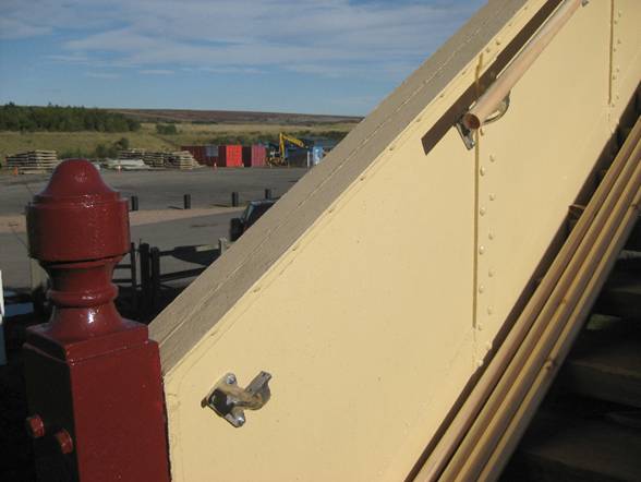
One
detail that had not been brought into use on 17 September was the
handrails. We had one or two complete
handrail support brackets, but, unsurprisingly, most had disappeared or had
been broken. Accordingly a further 32
were cast though this time in aluminium alloy rather than iron. Here we see one of the supports in close
up. Frustratingly, the standard wooden
handrail sections were never of quite the correct length and recourse had to
be made to scarfed joints in order to complete the work.
7720
- 25
Sep 2010
|
And that, we think, just about concludes the story of
the footbridge, there are some minor jobs to do, like pouring the concrete
thresholds, fitting smoke hoods, fitting wooden caps to the tops of the tower
legs, and we are even looking at the possibility of fitting lamps. We may or may not report on these smaller
matters. The images below are taken from
a series of high resolution images that we intend to make available to our
friends at the Rushden Historical
Transport Society near Northampton, and the Leicester Museum who have helped us
in one way or another over the last few years.
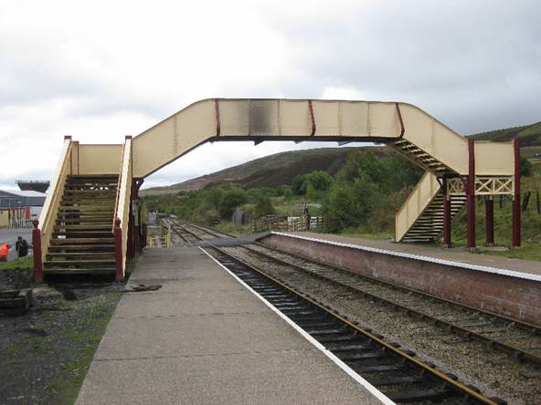
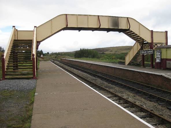
A
general view of the bridge from Furnace Sidings, platform 1, looking over the
level crossing towards the south and Blaenavon (High Level) station. The flight of steps to the left in the shorter
of the two and was originally on the Leicester (north) side of Hinckley station.
7756
– 3
Oct 2010
|
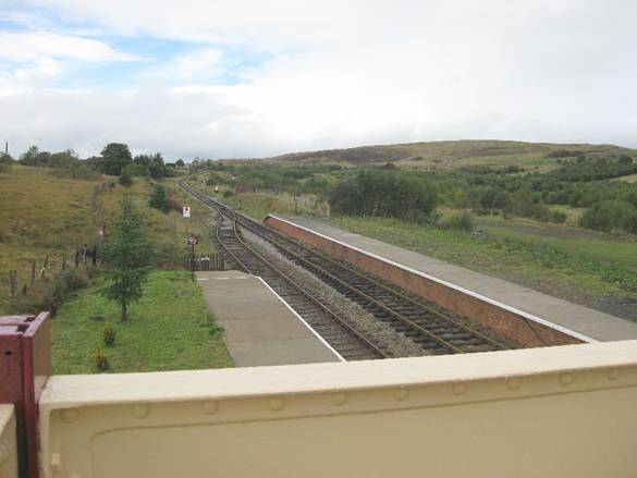
Looking
north from Furnace Sidings, platform 2 in the direction of Whistle Inn
The
flight of steps on the left landed on the platform for Nuneaton trains. The
smoke stains on the main deck are proof that steam engines are operating in
the area.
7757
– 3
Oct 2010
|
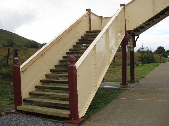
An
oblique view of the No2 flight shows the effect on both the inside and
outside of applying sandwich plates. We
think you will agree that once painted they don’t detract from the overall
look of the bridge at all.
7758
– 3
Oct 2010
|
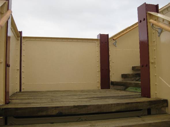
The
landing on tower 2. The remains of a
few setps were measured for thickness and varied between 75mm and 80mm. To be sure we standardised the planks at
85mm thickness – so they should last for a few years yet
7759
– 3
Oct 2010
|
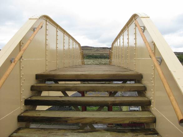
Standing
on the landing of tower 2 and turninf east we see the ascent steps to the
main deck
7760
– 3
Oct 2010
|
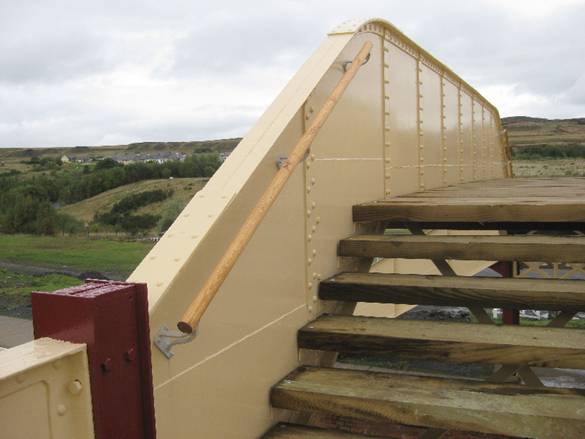
The
top of this tower leg awaits its wooden cap, whilst the newly cast aluminium
alloy handrail brackets await a coat
of paint.
7761
– 3
Oct 2010
|
A
view northwards towards the top of the line and the Whistle Inn station from
the landing of tower 2. The
environment in which the bridge finds itself is considerably more rural than
in Hinckley!
7762
– 3
Oct 2010
|
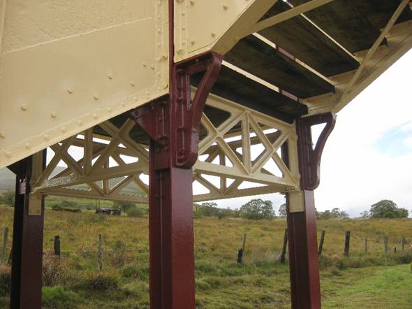
This
is a view looking roughly north-west up into the complexity of the top of
tower 2. The four cast trusses are now
easy to see, and add considerable charm to this rather austere structure.
7763
– 3
Oct 2010
|
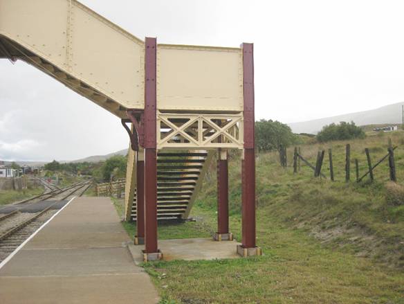
Another
view of tower 2 looking south from platform 2
7764
– 3
Oct 2010
|
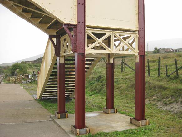
This
final close up view is of tower 2 looking south west.
7765
– 3
Oct 2010
|
Click HERE to return to Page 1
Click
HERE to return to Main Development page