DEVELOPMENT – Station building at Furnace Sidings (Step 1.3.3)
Click HERE to move
directly to page 2
INITIAL
PLANS (uploaded
The
need for a comprehensive station building at Furnace Sidings is well overdue,
the existing wagon body which serves as a passenger ‘waiting room’, despite
recent improvements, and the steel box that served as a ticket office are
completely inappropriate to meet the needs of our ever-increasing passengers
numbers. On the face of it, funding is now in place to permit the
construction of a long awaited station building at Furnace Sidings. Funding will come from funds directed to
construct the Big Pit branch. As yet no
building has started and there are few if any pictures. We have refined our plans over a number of
years, and at present they have been submitted to architects for evaluation and
comment – and probably complete condemnation!
All the same, we present some of our ideas here.
In the grand scheme of the Big Pit branch project,
the station building is not the highest priority, but we have managed to
convince our funders, the Heads of the Valleys programme (HoV) that it needs to be included and a relatively
small amount of money has been earmarked for the station building. We must however exert strict control over the
large and expensive elements of the project in order to prevent any cost
overruns on the large elements squeezing available funds for the station
building (and also the small amount earmarked for the footbridge)
Geography and position
The construction of station
building is expected to be start late in 2009.
It is to be installed on Platform 1 Furnace Sidings, and its position at
Furnace Sidings with respect to the completed second platform and the
footbridge, currently in progress, is shown in Fig.1
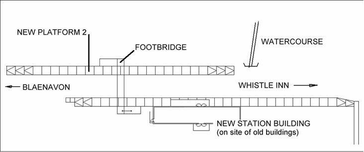
Fig.1 Platform 2 in plan,
together with other features
The requirements the station
building were considered to be that it should by simple enough to permit construction by relatively unskilled
labour, sufficiently modular to permit easy expansion if need be, and provide
all the facilities passengers might need in the foreseeable future. It must be durable, and have a high
resistance to damage both from the weather and vandal attack. Additionally there was a requirement the
costs were not so high as to jeopardise funding for other parts of the project,
and simple enough to permit relatively short construction times by PBR
volunteers. The remains of
The design chosen was
inspired by the ‘tin chapels’ which were once common in
The general form of the
building is rectangular in plan with a simple gable roof. Each side of the building supports a
canopy. The entrance canopy (on the side
opposite the platform) is relatively short, whilst on the platform, where
passengers are likely to choose to wait, the canopy is rather longer. The building is designed to encourage
passengers to approach the building from the side opposite the platform and
enter the building through double doors into a hall roughly halfway along the
building. Doors either side of this hall
lead to a shop, displays, lavatories and a large tearoom. The windows are positioned so that each may
be closed by means of an outside steel shutter with hinges angled so that the
shutter falls inside the window frame when closed and just proud of the outside
wall when open. In the open position the
appearance will be somewhat akin to a Swiss chalet, though it is planned that
the rear face will be used to display timetables and posters etc., which will
be seen by passengers when the shutter is opened. From the ticket office a window opens into
the hall, a second window opens directly onto the platform. If weather conditions so dictate one or both
of the normal entrance doors (on the East side) can remain closed and
passengers may enter the building directly from the platform, again, weather
conditions will dictate from which window the ticket office can issue
tickets. The design is also optimised so
that the tearooms and kitchen can be added at a later date – rudimentary
tearoom facilities exist already on site.
The proposed station building is planned to be 25.4m long x 5.4m wide
(83ft 4ins x 17ft 9ins), and is shown in plan in Fig.2 below.
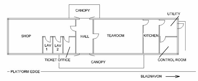
Fig.2. Station building plan
Fig.3 below shows the
building viewed from the proposed platform 2 and facing east. Every window is protected by a steel shutter,
and the double doors themselves are effectively steel shutters. The window shutters are marked with diagonal
crosses. The shutters open outwards and
are carried on carriage hinges. Since it
is intended that they are closed and made fast from the inside, then it is
likely that the windows will have to be of casement type, and must me made to
open inwards. Two small high windows are
shown to the left of the doors, and are coincident with lavatories. It is planned that the windows are glazed
with wired obscured glass or polycarbonate so that shutters are less
necessary. Since the drawing is for
information only, no overhanging eaves are shown, also the wall cladding is
shown extending only to the top of the dwarf wall, when it is planned to extend
it downwards by a further 50mm or so.
Note also the slope of the platform, which is seen to be considerable
when compared with a level datum. It is
sufficient to require that special arrangements to be made at the end door, to
permit safe access
Fig.3 Elevation towards the east
(ie platform side)
Fig.4 below shows the
building viewed towards the west from the ‘paddock’. When suitable pathways are built, this will
provide the normal passenger entrance when the weather is good. Again, two views are given – the upper view
with the cladding, the lower view with the cladding removed. The doors are shown closed, but when opened
the doors will fold across outside of the building leaving little spare room
for windows, or any form of decoration.

Fig.4 Elevations towards the west
Fig 5. also below, shows the
end elevations – both clad and unclad.
In the sketch on the left, (looking up the line) note the ‘woman’ who is
1.575m (5ft 2ins) tall. She is standing
at the foot of the access ramp to the door.
The line behind her is the level of the platform at the main entrance
doors. On the sketch on the right,
looking down the line to Blaenavon, the ‘man’ is 1.828m (6 feet) tall, but
appears to have no feet. That is because
he is standing outside the main entrance doors, and the slope of the platform
hides his feet from view.
Fig.5 End elevations –looking towards
the Whistle Inn on the left, towards Blaenavon on the right.
Fig. 6 shows the sort of
thing PBR might see as the station is approached from the south. The figure was drawn when the direction of
the flights of steps was undecided; on the left the flight of steps is towards
the viewer, on the right it is on the far side of the bridge. There may also be some adjustment of the
height – there is plenty of clearance for rolling stock, and any reduction
would make the bridge easier for pedestrians as well as reducing wind
resistance,
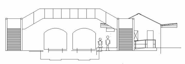
Fig.6 Impression of view from
south of the footbridge if it is installed at the proposed position.
Impressions
These computer generated
models were derived at various stages and represent differing stages in realism
as something approaching the final design was realised
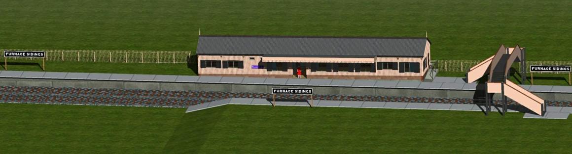
This is an overall view of the platform is a
high-level elevation looking east. It
shows the relationship between the bridge and the building. The window shutters are shown, and the long
west side canopy is shown, though it is not particularly clear in this
view. Inside the double door the ‘lady
in red’ attempts to show the scale
|
|
This early attempt at modelling the station
building is important because, despite the colouring being completely
incorrect, it does at least show the short canopy on the east side. The valancing on the canopy is not shown,
nor are the window shutters |


More refined views of the south end of the building –
during the day, and at night

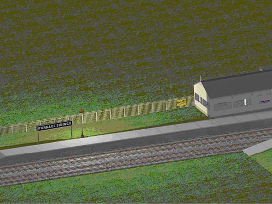
The north end of the building. The left hand image is relatively unfinished
but the longer view on the right, shown at night, is more developed
Things are beginning to move
Click HERE to
continue to page 2
Click
HERE to return to main Development page
![]()